Recently, I spent some time reading papers / UE4 shaders code / various web pages about skin shading models. It was very interesting and I've got some achievements which I want to share.
Sub Surface Scattering
Skin is translucent surface and usually rendered with shading models based on scattering theory.
Light enters at some point and travels inside of translucent tissue and comes out at other point. This looks simple but needs some tricks to work in real time renderer.
Diffusion Profile
All of proper skin shading models are based on this theory and data. It describes how light is scattered along the distance from incident point.
People measures data how much light is scattered using real skin.
 |
| Perpendicular laser on real skin |
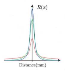 |
| Different diffusion curve among color channel |
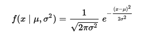 |
| Using Gaussian function to fit this curve |
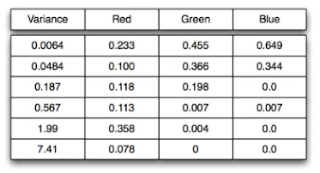 |
| Actual fitted gaussian parameters |
And the curves are fitted to sum of gaussian functions. this fitted function is used to blur adjacent diffuse color pixels or to pre-integrate diffuse BRDF texture. I was curious that are there any measured data from asian or african american on the internet but got no success. What about some alien whose blood is blue? Maybe I should worry later about this.
Screen Space Sub Surface Scattering
Jorge Jimenez's method.
http://www.iryoku.com/sssss/
The core ideas is blurring diffuse irradiance in screen space using fitted gaussian kernel. Of course blur distance is adjusted according to depth and angle to be accurate.
This technique is well suited to deferred renderer and the quality is very good.
But some people would not agree this is the best method due to the low quality of low default diffuse irradiance and too much blur look. but this is still great skin rendering method.
I didn't do much research on this because UE4 version of this(SubSurfaceProfile) is perfect in my opinion.
Pre-Integrated Skin (Penner)
Another popular method is Penner's Pre-Integrated Skin.
https://www.slideshare.net/leegoonz/penner-preintegrated-skin-rendering-siggraph-2011-advances-in-realtime-rendering-course
The basic idea is to assume skin surface as circle and integrate diffusion profile according to two parameter(incicent angle and curvature of skin surface). He thinks that these two factors are most important parts of skin scattering.
This generates texture like below.
Actual hlsl shader code would be like,
float3 ScatteredLight = Texture2DSampleLevel(PreIntegratedBRDF, PreIntegratedBRDFSampler,
float2(saturate(dot(N, L) * .5 + .5), Curvature), 0).rgb;
|
U : indexed by cosine
V : indexed by r(curvature)
There are many other details in this technique, but the basic idea is like this.
UE4 version of Pre-Integrated Skin Shading model
The overal structure is same,
-Pre-integrated BRDF texture(index by cosine and curvature like parameter)
But there are several difference between UE4 version and original.
-Pre-Interated Skin BRDF is applied only on shadowed region.
Unshadewd region is shaded by default lit(this is incorrect and make skin too bright)
-BRDF texture doesn't have different diffusion profile among color channel(frequency)
 |
| Texture tone is gray |
BRDF texture contains grayscale(same diffusion among color channel) and multiplied by subsurface color provided by artist.
Actually subsurface color by artist is not that bad idea. But it is very difficult to make realistic human skin using UE4's pre-integrated skin shading model.
I think this is why epic recommends SubSurfaceProfile model as high quality skin rendering.
By proper implementation according to oroginal paper, we can get below.
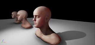 |
| My implementation |
Due to the limitation of deferred renderer, I could not implement normal bluring, It could look a little bit harsh with rough normal map. but it was ok with our art direction. (we could control our normal map).
Translucency
With these two methods, rendered human skin already looks like skin. But we need more.
Because skin is translucent tissue, incident lights actually transmit through thin parts.
And should have effects like below,
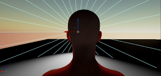 |
| light transmitted through thin ear. |
And Jorge Jimenez wrote paper about this.
The most important idea is calculating thickness from light incident point to actual shading point. With this thickness we could know how much light will transmit through.
We know these two points in shadow projection shader. (Shadow depth value and shaded world point)
Actually, UE4 is already calculating this transmittance value and define this as "Sub Surface Shadow Term". This term is usually multiplied to various subsurface lighting terms.(ex: TWO_SIDED_FOILAGE). But it seems that both of two skin shading models lacks this effect.
So I added translucency effect of Jorge Jimenez to Pre-Integrated skin shading model.
 |
| With environment lighting |
Due to the shadow depth range precision issue, It seems that spot light is most accurate for calculating thickness(transmittance or sub surface shadow term). Point Light lacks this feature.
Skin BRDF with Indirect Lighting
All of the above methods are for direct lightings. Sometimes game characters could be in lighting conditions which have only indirect lighting(shadowed region). Then all of these fancy skin shading will disappear.
UE4 multiplies subsurface color to diffuse irradiance(from Spherical harmonics probe). It could be ok with that. But there is something we could do for this sad situation. The graphics programmers in Ready At Dawn suggest excellent technique for applying skin BRDF with indirect probe.
The idea is like this,
We use clamped cosine as transfer function which will be dotted with irradiance spherical harmonics probe. This is zonal harmonics coefficients projected to represent clamped cosine function.
The idea of RAD programmers is to use special zonal harmonics transfer function which is projected to represent diffuse skin BRDF. They explained their idea kindly in there paper.
http://blog.selfshadow.com/publications/s2013-shading-course/rad/s2013_pbs_rad_notes.pdf
I implemented this and below image is generated zonal harmonics coefficients indexed by curvature.
X axis is curvature and Y Axis are zonal harmonics order.
 |
First row : order 0, Second row : order 1, Third row : order 2
x axis : surface curvature
(with 30000 randome sample during monte carlo integration) |
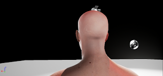
And this is the result. The result was quite impressive.
You can compare with normal diffuse irradiance from light probe.
Lighting condition used.
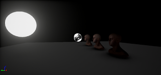 |
| Emissive sphere and 1 light probe(no direct light) |
3 zonal harmonics coefficients are projected using below generation code.
Order 0
_func = [this](double theta, double rInv)
            {
                float R = rInv * 255;
                float radius = 2.0f * 1.f / ((R + 1) / (float)SizeX);

                float cosTheta = FMath::Cos(theta);
                auto BRDF = IntegrateDiffuseScatteringOnRing(cosTheta, radius);

                return 0.28209479177 * BRDF.X *sin(theta);
            };
            D0R = 2 * PI * MonteCarloIntegral1D(0, PI / 2, NumMonteCarloSample, rInv);
Order 1
_func = [this](double theta, double rInv)
            {
                float R = rInv * 255;
                float radius = 2.0f * 1.f / ((R + 1) / (float)SizeX);

                float cosTheta = FMath::Cos(theta);
                auto BRDF = IntegrateDiffuseScatteringOnRing(cosTheta, radius);
                return 0.4886025119 * cos(theta) * BRDF.X * sin(theta);
            };
            D1R = 2 * PI * MonteCarloIntegral1D(0, PI / 2, NumMonteCarloSample, rInv);
Order 2
_func = [this](double theta, double rInv)
            {
                float R = rInv * 255;
                float radius = 2.0f * 1.f / ((R + 1) / (float)SizeX);

                float cosTheta = FMath::Cos(theta);
                auto BRDF = IntegrateDiffuseScatteringOnRing(cosTheta, radius);
                return 0.31539156525 *  (3 * pow(cos(theta), 2) -1) * BRDF.X *sin(theta);
            };
            D2R = 2 * PI * MonteCarloIntegral1D(0, PI / 2, NumMonteCarloSample, rInv);
I used skin BRDF integration from this
link.
I think maybe there will be more advanced skin rendering technique later. But these are best for now.


